
CLASSIFICATION

Pockels Cell Driver
Categories:
The Pockels Cell Drive controls the Pockels Cell by applying a high voltage for rapid switching. Precise working pulse width and frequency can be set through the signal generator. It has two control modes, namely the conventional mode and the analog voltage mode. The amplitude of the output voltage can be adjusted by turning the knob, and the amplitude of the high-voltage output can also be adjusted by inputting an analog voltage. The drive integrates a high-voltage power supply and a high-voltage pulse modulator. With a full-metal shell, it is convenient for integrated application in laser systems and has a long service life.
Product Applications:
Drive Pockels Cell
Product Features:
High maximum output voltage
and wide adjustable range of pulse width.
Short rise/fall time and small overshoot/undershoot voltages.
Two control modes: conventional and analog voltage.
Product model and technical parameters
Pockels Cell Drive(PCD-S5-1-E-S) | Waveform | ||
input | Power supply | +24VDC,1A(Provide AC adapter) |
|
Trigger level | +5V(50 Ω , SMA interface) | ||
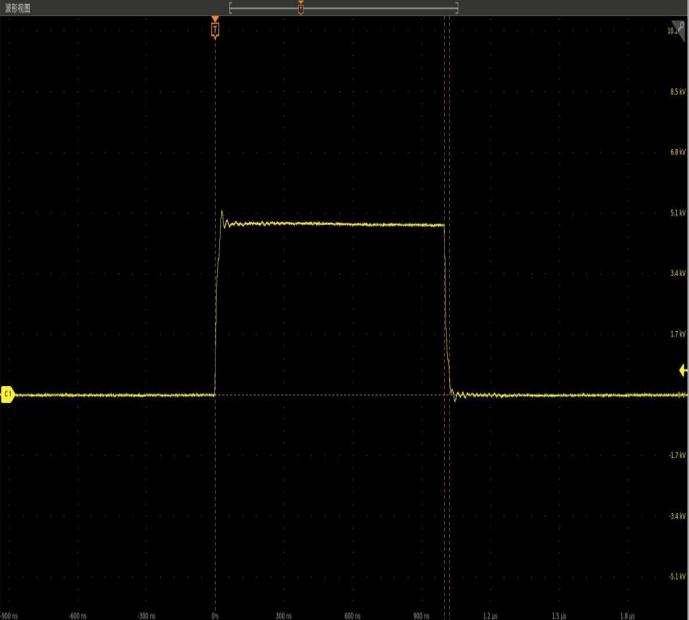
output | Pulse waveform | square wave | |
Pulse amplitude | 0〜5kV | ||
Pulse width | 200ns〜1us | ||
Repetition frequency | ≤1kHz | ||
Rise time | ≤20ns | ||
Fall time | ≤20ns | ||
Load capacitance | ≤10pF | ||
environment | Operating temperature | +10℃〜+35℃ |
|
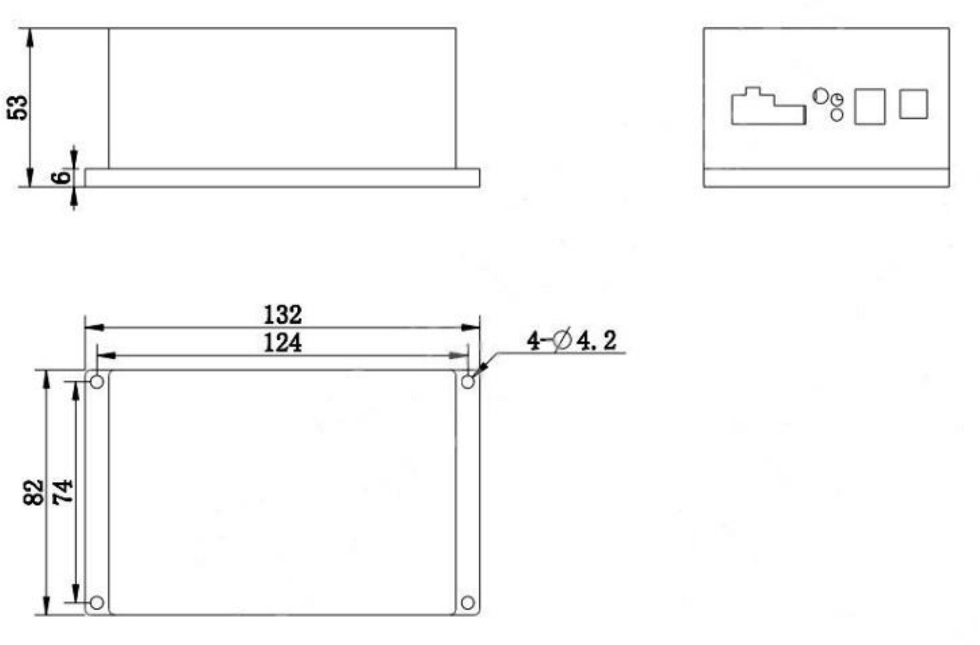
appearance | Drive dimensions(L×W×H) | 132mm×82mm×53mm | |
Precautions:
1. The Pockels Cell Drive can generate high voltage. Please abide by the principles of safe electricity usage when using it to avoid dangers such as electric leakage and electric shock.
2. Make sure that the high-voltage power supply and the modulator are properly cooled.
3. Do not turn on the drive without a load.
4. Ensure that the power supply is turned on first before inputting the trigger signal.
5. Do not use the conventional control mode and the analog voltage control mode of the drive simultaneously.
6. Since it takes time for the capacitor to discharge, do not touch the high-voltage output interface of the drive immediately after turning off the Pockels Cell Drive until it is completely discharged.
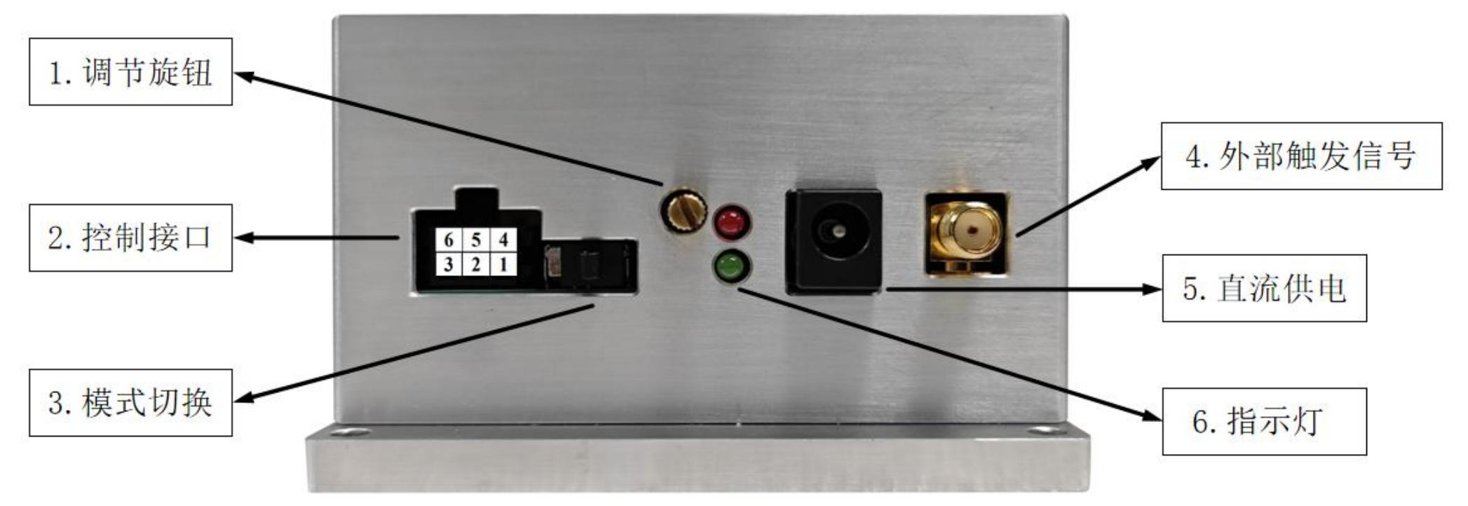
Interface
接口 | 定义 |
1.Adjusting knob | It is only used for the conventional control mode. Rotate it clockwise to increase the high-voltage amplitude, and rotate it counterclockwise to decrease the high-voltage amplitude. |
2.Control interface | only used for the analog voltage control mode |
(green)High-voltage amplitude setting: The analog voltage input to PIN1 determines the amplitude of the high-voltage output. Approximately 1V corresponds to 1kV. | |
2, 5(black)Ground for power supply and interface | |
3(void) | |
4(blue)High-voltage enable:+5V voltage enables the high-voltage output,0V shuts down the high-voltage output. | |
6(red)High-voltage monitoring: The output voltage at PIN6 is the monitoring signal for the current high-voltage amplitude. Approximately 1V corresponds to 1kV. PIN6 can be used in both the conventional control mode and the analog voltage control mode. | |
3.Mode switching | Change control mode.Left side: Analog voltage control mode; Right side: Conventional control mode. |
4.External trigger signal | Connect to the external trigger signal. Connector model: SMA. |
5.DC power | Connect to an external +24V DC power supply. Connector model: DC-005-2.0mm |
6.Pilot lamp | Green: Power supply is connected; Red: High voltage is being output. |
Specification( mm)
CONTACT US


Email: sales@crystech.com
Tel:+86-532-88703980
Fax:+86-532-88703982 ext.1515
Headquarter:
Keyuanweisi Road 102, Qingdao 266101, China
Production base:
Xianshan East Road 18-B, Chengyang District, China

QR code
Powered by www.300.cn Business license © 2024 Crystech Inc
Please fill in the following information, and we will send you the required information within 24 hours.
You can also directly contact our product experts at +86-532-88703980